If you have followed our Facebook page, you’ll probably know that we have upgraded our MIP backlighting. We haven’t really covered the process in great detail on our Facebook page, so we’re writing a more detailed post here.
Motivation
First of all, it’s important that you understand why we decided to upgrade and redo our MIP backlighting. There are mainly two reasons; Safety and the quality of dimming and backlight. The previous backlighting-system wasn’t the best in regard to safety. This system used an MDF backer piece which the led strips were mounted to. There were also a lot of un-protected solder points and lots of small pieces of led strips which contributed to a lot of extra cabling. Mounting of this MDF backerboard wasn’t great either. Here there were used double-sided tape and electrical tape. This meant that the backlighting could move over time, and the risk of shorting were therefore quite high. We wanted a safer system where this wouldn’t be an issue any more.
The dimmer curve on the previous system wasn’t too great either. We wanted a more linear dimmer curve than the cheap PWM dimmers managed to do. The old dimmers were also not the best in regards to safety, because we took them out of their casings and laid them inside the backlighting box (which were already there) of the lower MIP. There were also a lot of use of Wago connectors, which made cable management quite difficult.
How we decided to do it
After a lot of research, we decided to not buy existing products, but rather build the things needed by ourselves. When we did our research, we discovered a dimmer, made by Ed Kooevar , which looked rather promising. Therefore, we had a look into how we could integrate them with our simulator and came to a conclusion that it would probably be best if we made them into PCB’s. As a result, we also wanted to have something to distribute power for the captain’s main panels and first officer’s main panels. We did also mount a 5v 4 channel relay to control when the backligting should be on or of in regards to the aircrafts state.
The reason to why we went with boxes to attach the ledstrips, is simply because we thought that this would be a neat solution. The previous owner of our sim (look at the blog post “A little update” for more information) had made 3D printed boxes for the lower MIP panels, and this was working great, so why should we reinvent the wheel, when we have something that’s works and looks great? Another great benefit of using these kinds of boxes is that all of the electrical connections are enclosed, which makes shorts less prone to happen. It’s also reducing light-pollution in the back of the MIP, which makes night time flying a better experience.
PCB - Dimmers and distro
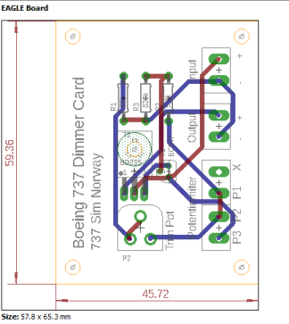
As mentioned earlier, we decided to go with custom made PCB’s for dimming and distribution. We designed the PCBs ourselves in a software called Eagle. This is a free Autodesk application used to design circuits and PCB’s. It took some time to learn the software, however when we started to get the hang of it, the designing-process became pretty easy.
The circuit boards were ordered as prototype boards from JLC PCB. The price including shipping was good, and the manufacturing time was quite fast to. The PCB’s were manufactured over a weekend, and we got them after around two weeks. The quality and service was exceptional! The PCBs gives the whole project a more professional look.
Dimmer
The dimmer is a simple voltage regulator configured as a classical emitter follower circuit. The circuit is capable of at least 500 mA output current. You could change the transistors to extend the output range to higher values, however, this would make the circuit considerably larger. You could also solder the circuit directly to a potentiometer, but since we wanted to keep the dimmers more accessible, we made them independent in the form of PCBs.
“The circuit is a standard emitter follower using two NPN transistor in Darlington configuration. The supply voltage is 12 ± 1 Volt. P1 will regulate the intensity whereas P2 can be adjusted to minimal intensity so the complete range of P1 can be used from zero to full intensity. Comparable types of transistors may be chosen. The regulating P1 may be combined with a switch. The maximum quiet current is about 0,1 mA.”
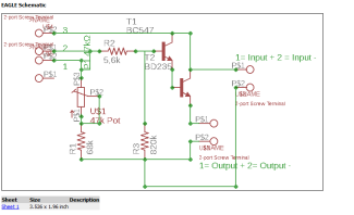
Source: Ton de Bruijn – Moerkapelle (The Netherlands)
Components:
Dimmer schematics
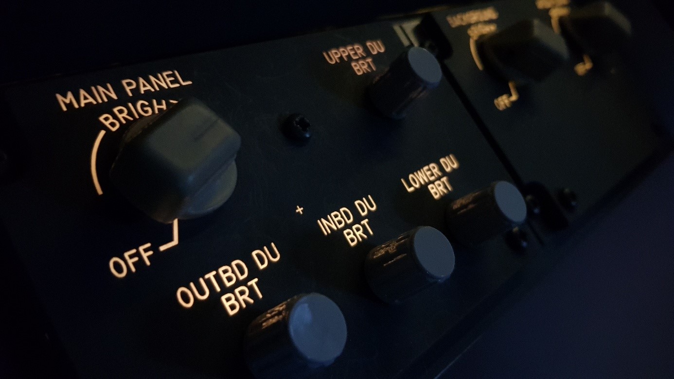
- P1 – Potentiometer 47 kΩ with switch
- P2 – Trimming potentiometer 47 kΩ
- R1 – Metal film resistor 68 kΩ / 0,25 W
- R2 – Metal film resistor 5,6 kΩ
- R3 – Metal film resistor 820 kΩ
- T1 – NPN silicon transistor BC547C
- T2 – NPN silicon transistor BD235
- 4 2-port Screw Terminals
One advantage to using PCBs is that it’s a lot easier to solder the parts together, and to get the circuit to work properly.
Distribution cards
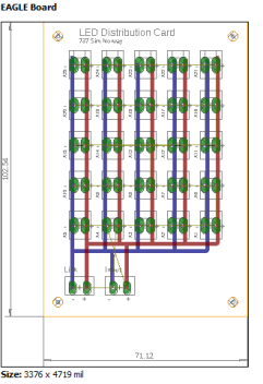
The distribution cards are in many ways a lot simpler than the dimmer card. The distribution cards are simply connectors connected in parallel with an input and link. We wanted to have these distribution cards to avoid having to many cables going into the dimmer cards – especially if we want to do the same in the overhead as we have done in the MIP. Therefore, the basic purpose is to make cabling easier.
Components:
- 25 2-pin connectors (Would probably work better with 2-port screw terminals in the long run)
- 2 2-port screw terminals
3D Printed Boxes
The process of making the 3D printed boxes was quite easy. We used a software called Fusion 360 by Autodesk to create the files which were necessary for the 3D printer. The 3D printer we use is an Anet A8.
The boxes were created so that we were able to use the existing screws in the MIP. As the screws were a bit short, we changed them to a length of 25 mm.
To mount the LED strip to the boxes, we used the adhesive tape on the back along with some hot glue, to keep them secure.
Result